Torque Sensing


The MagCanica torque sensor system’s ability to provide laboratory-grade accuracy while simultaneously being able to operate at extremely elevated rotational speeds (up to 140,000 RPM proven, up to 200,000 RPM anticipated) is made possible through its truly non-contact magnetoelastic technology. This technology eliminates the use of strain gauges or phase shift/twist measurement and with them the various limitations of these methods, discussed in more detail here.

Phase 1

Circular Magnetization of a Section: A section of the shaft (or ring in some cases) that torque is being applied to, is magnetized in a circular direction one single time prior to use so that it remains circularly magnetized even when no torque is present. This process is the key to the non-invasive aspect of the system as the shaft can now act both as a mechanical torque transmission member and as the primary transducer of the torque sensor system.

Phase 2/3

Phase 2:
Reorientation of Circularly Magnetized Field: When torque is applied, each of the magnetic domains comprising the circular magnetization is reoriented in proportion to the direction and amplitude of the applied torque as a consequence of a physical principle known as the inverse Wiedemann effect.

Phase 3:
Formation of an Externally Detectable Magnetic Field: Upon application of torque, the cumulative reorientation of each magnetic domain in the magnetized section of the shaft results in the formation of an axial component of the (previously, under no applied torque) circular magnetization. This creates an externally detectable magnetic field emerging from the ends of the shaft. As a consequence, an axial magnetic field – similar in shape to that of a bar magnet – that is directly proportional to the torque applied, is now present externally to the shaft.

Phase 4

Measurement of the External Magnetic Field: Due to the linear proportionality between the torque applied and this external axial magnetic field, a truly non-contact measurement of the torque is achieved by simply measuring the intensity of the external magnetic field using magnetic field sensors and associated signal conditioning circuitry.

Application of the four phases

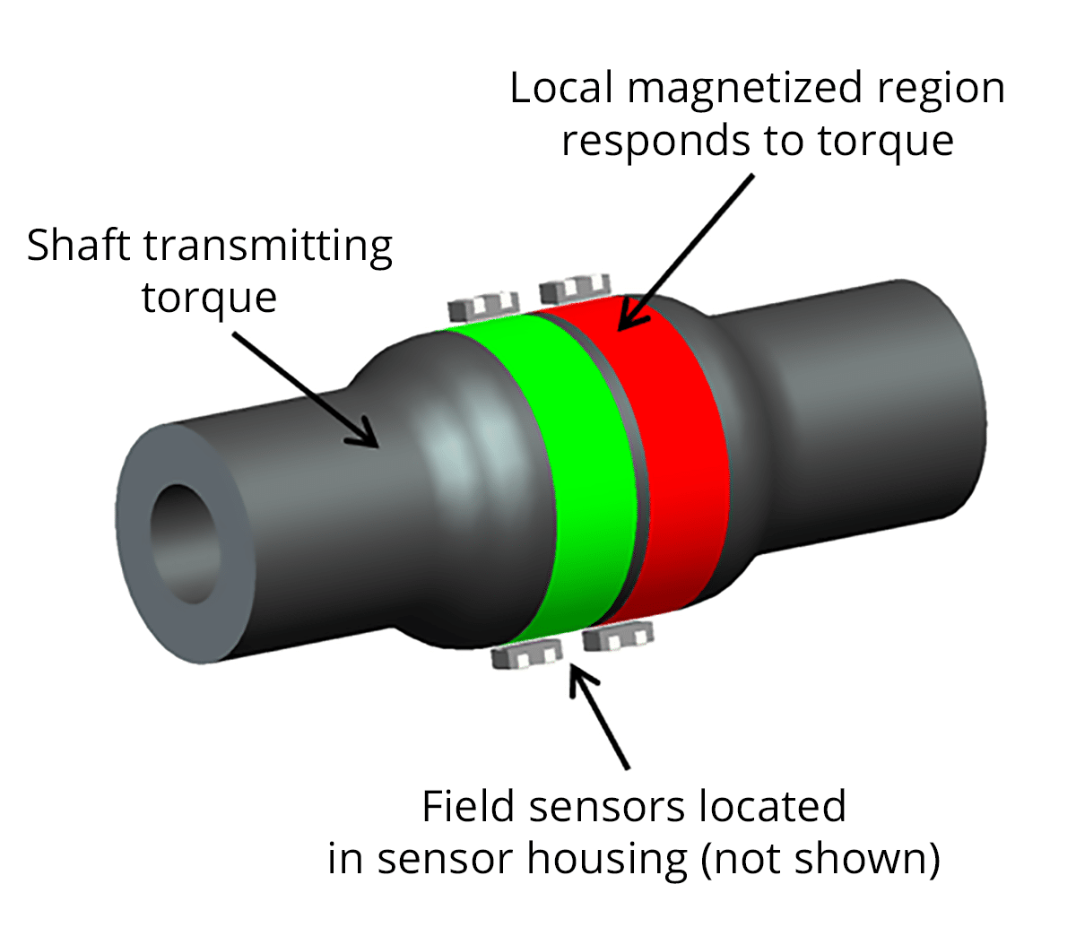
MagCanica’s technology is based on the combination of these previous four phases. Prior to entering into service in the field, and one single time only as part of a one-time process, the shaft transmitting torque is magnetized circumferentially in a local region, allowing that portion of the shaft itself to become the transducer. Now the shaft can both transmit torque, and act to provide a measureable signal allowing that very torque to be measured. In order to accomplish this, the shaft needs to be made of a material that provides these magnetoelastic properties. It happens that these properties are available in standard steels already used within many commercial applications. If the existing shaft is not made of one of these materials, it is often the case that the shaft can be manufactured from a suitable material with appropriate mechanical and magnetoelastic properties, often with preferable strength and component life characteristics. Depending on the material and the material’s magnetoelastic properties, a local region on the shaft is sized to provide a specific amplitude of maximum allowable torsional stress at the peak operating torque for the application.

The picture indicates the local region that might be sized differently from the nominal diameter of the shaft by the increased diameter in a specific region. The green and red colors indicate oppositely polarized magnetized bands. The field sensors, indicated above without a housing, would in a real installation be packaged within a housing typically made of a high performance plastic that rides directly on the shaft (for applications running at 3,000 RPM or less), or aluminum in which the sensor housing does not contact the shaft directly (for speeds above 3,000 RPM). Different sensor constructions designed for different applications and installations are shown in the Products page.

Advantages of MagCanica’s Torque Sensor Systems vs. Competing Technologies

  • Minimal impact on driveline rotordynamics (does not require a separate torque measurement shaft)
  • Does not require rotation to work (can measure even at 0 RPM) 
  • High reliability as nothing is bonded or attached to the shaft
  • Does not emit nor is sensitive to RF signals
  • Inherently non-contact means of measurement
  • Outstanding frequency response and dynamic torque measurement (up to 4.5 kHz)
  • Scalability (from the milli Nm range to the mega Nm range)
  • Direct applicability to shafts made of existing automotive and aerospace steel alloys
  • Package size and mass typically much smaller and more packageable than other types of torque sensor constructions.
  • Packaging flexibility as the magnetic field sensors can be positioned in myriad ways.

Competing Technologies

Measurement of Surface Strain:


The conventional method for measuring torque in which a piezoresistive (a material that changes resistivity depending on strain) strain gauge is attached to the rotating shaft. As a result, any changes in strain from torque are recorded as variations in an electric signal. 

Disadvantages:

  • Reliance on torsional strain inhibits their application to shafts of arbitrary torsional stiffness and often limits their ability to provide a frequency response above 1kHz
  • Strains are too small (at most a few parts of 1000) to be measured directly, so complicated workarounds must be established: conventionally, four gauges are arranged in a Wheatstone bridge circuit
  • Slip rings or local telemetry are required to feed a continuous current to the gauges and acquire the signal from the bridge circuit. The use of slip rings can act to limit the maximum RPM of the shaft, and wear can significantly reduce system reliability. The use of local wireless telemetry can limit the maximum bandwidth of the system, and can either be prone to signal drop-out or create significant electromagnetic emissions that may interfere with other sensors, electronics, and telemetry on the vehicle.

Measurement of the Twist Angle:


A pair of identical toothed disks attached at opposite ends of a portion of the shaft enables a ‘twist angle’ to be determined from the phase difference between them through an optical or magnetic measurement, which in turn enables torque to be calculated.

Disadvantages:

  • Requires the shaft to be rotating
  • Requires a slender portion of the shaft to enhance the twist (several degrees at most for a length-to-diameter ratio L/D = 5)

Permeability-Based Magnetoelastic Torque Sensor:


Readings for torque are achieved through the measurement of changes in magnetic permeability that occur on regions of the shaft surface as a result of torsional stress from the applied torque. These variations in permeability are generally measured by encircling the shaft in some pattern of coils of wires and observing differences in induced voltages.

Disadvantages:

  • Permeability does not depend exclusively on torque and will vary with frequency, temperature, and magnetization
  • Permeability is neither an intrinsic property of the magnetic material nor a single-valued, structure sensitive property
  • Local variations in magnetic properties of typical shaft surfaces limit the attainable accuracy
DUAL ENCODERSTRAIN GAUGESAWMagnetoelastic Permeability
Based Technology
MagCanica’s Method -
Magnetoelastic Remanent
Circumferential Technology
Non-contactYESNONOYESYES
Torsionally stiffNONONOYESYES
Independent of T without need for compensationIn some casesNONONOIn some cases
Radially MountableYESNONONOYES
Package-able in motorsport race conditionsNONOIn some casesIn some casesYES
Frequency response500 Hz1kHz1kHz2 kHz4.5 kHz