Our culture at MagCanica has always been focused on the accuracy of the sensor when installed in the vehicle and when used under typical operating conditions. When discussing errors with our customers, we prefer not to focus on ‘Accuracy Class’ or designations that classify errors separately such as temperature, those associated with non-torsional loads, and only test by considering the application of carefully controlled loads. While these classifications do have a place, when they are the key focus and objective, in our opinion they mask just how accurate the sensor will be when installed in your vehicle.
The UHA high-accuracy drive-shaft torque sensors have been developed over many years, with the goal of achieving ‘laboratory grade’ accuracy while operating in-vehicle, not under controlled laboratory conditions. Our goal has been to develop a sensor that is better than 0.25% accuracy of reading (above a minimum threshold as the % reading when close to 0Nm becomes unrealistic) when operating in its final installation environment on a vehicle. The accuracy should be evaluated with realistic loading scenarios (e.g. lap simulations as well as conceived worst-case conditions), over the full-range of operating temperatures, when exposed to all possible vibrations, and with standard acquisition equipment suitable for use in a vehicle.
To meet these goals, the UHA sensor was designed to minimize each potential source of error:
- Errors associated with variations in the relative position between the sensor and shaft are eliminated by riding on the shaft.
- Errors associated with external magnetic fields are reduced by using highly effective shielding and a ‘keep out zone’ between the sensor and nearby ferromagnetic objects.
- Temperature and hysteresis errors are minimized through extensive testing of each sensor, and the use of sophisticated compensation models that run real-time on the integrated DSP.
- Unlike other technologies, bending stresses are fundamentally rejected and do not interfere with the measurement of torque.
- Signal transmission errors are eliminated by using a CAN output

Figure 1 First generation
high accuracy drive-shaft sensor
While much of our efforts to design and test the system do use controlled tests to quantify the errors and improve the system, extensive dyno and track testing have also been critical to its development in particular in regards to evaluating reliability. The first generation UHA sensor (then branded the BOP sensor) was designed in 2016 and tested in 2017 through a combination of development within MagCanica and through the use of dyno and track tests. Internal developmental testing at MagCanica consisted of extensive development time with both our torque testing rigs used to apply torque and our speed testing rig to test the durability of the integrated bushings. Testing outside of MagCanica consisted of numerous dyno and track tests.

Figure 2 Second generation
high accuracy drive-shaft sensor
The design was quickly iterated upon in order to optimize the package and improve reliability. This second generation design allowed the sensor to be radially installed onto the shaft, allowing the use of integrated tripods on the shafts. Sealing was provided with a custom bushing and seal design. MagCanica’s latest generation of electronics was integrated. The weight was cut by ~100 grams. Both internal testing, as well as dyno and track testing, confirmed the improvements, as we received excellent feedback in regards to both reliability and accuracy.
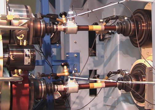
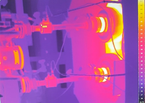
In addition to shorter-duration dyno and track tests, we were highly focused on ensuring excellent reliability even during the use within 24-hour endurance races. As testing of this duration is not easy to come by, MagCanica partnered with a premier motorsport supplier, Pankl Racing Systems, to carry out a full 24-hour dynamic dyno test, applying full lap simulations which included drive-shaft dynamics associated with suspension travel and representative temperatures. This testing was completed successfully without any reliability issues.
Since 2018, the development work on the UHA has continued, focused on further improving accuracy through complex modeling and signal correction algorithms carried out within the firmware.
Design and production of the UHA sensor and dynamic dyno testing

Figure 3 Image of two UHA sensors installed

Figure 4 Image of the two UHA sensors
while being monitored with a thermal camera.
