Shortly after MagCanica incorporated in California, we learned of the need for torque-measurement on the U.S. Navy’s Landing Craft Air Cushion (LCAC) hovercraft. The LCAC drive train consists of two turboshaft engines (MTU/Vericor ETF40B) on the starboard and port sides of the craft combining through right angle and offset gearboxes to drive lift fans and propellers. Note that the following figures and summary are cited from a joint MagCanica / Navy publication published as part of the 2012 ASME Turbo-Expo (link to 2012 paper). The drive train right-angle gearbox of the LCAC has a maximum operating torque limit of 1600 lb·ft (2169Nm) whereas there is a spread in the power output of one engine to the next of up to 20%, and the best performing engines can exceed the rated capacity of the gearbox. While the fuel flow could be increased in the underperforming engines to produce more torque, without a means of measuring torque, it was necessary to limit the torque of each engine by assuming it was one of the best performing. Limiting torque was previously based on torque lookup tables which penalize the overall performance of much of the fleet due to a significant variance in engine output horsepower. This sub-optimal operation of the craft could be overcome by measuring actual torque produced by each engine with an onboard torque-meter; however conventional torque-meter designs were deemed impractical to retrofit due to the design requirements, and issues with integration and reliability / maintainability. An in-depth search by the US Navy identified a torque-meter concept utilizing magnetoelastic polarized band technology, that could be developed by MagCanica.
There are specific attributes of the magnetoelastic polarized band torque-meter technology that made it well suited to measuring torque on a turbo-shaft engine:
- Non-contact between the sensor and the shaft
- Insensitive to rotational speeds
- High allowable shaft torsional stiffness (the LCAC shaft twists less than 1 degree even at max torque)
- Low cross-sensitivity to temperature
- Low mass and compact size

Figure 3 Schematic diagram of the
LCAC representing the desired
location of the torque-meters in the LCAC
.
Despite these compelling advantages of the magnetoelastic polarized band technology, it carries with it certain restrictions that have to be overcome:
- Ability to Retrofit to Existing Hardware. This was a key requirement, i.e. to be able to instrument the existing engine output shaft without the need for any substantive modification to the existing shaft or surrounding components, given that the LCAC fleet was already in service and significant investment and infrastructure had already been made in the historical architecture of the engine output environment, also known as the Inlet Housing Module (IHM).
- Positional containment. Relative radial and/ or axial movement of the shaft with respect to the sensor housing assembly measuring the magnetic field needs to be controlled. This relative movement of the transducer shaft versus the housing upon which the sensor could be located was well constrained within the LCAC.
- Magnetic environment. The presence of ferromagnetic components in very close proximity to the torque sensor housing assembly or to the transducer shaft during system operation, or the use of ferromagnetic tools in very close proximity to the torque sensor housing assembly or transducer shaft during system assembly or repair, can be detrimental if not properly controlled. While there were ferromagnetic components relatively close to the sensor in the LCAC installation, magnetic shielding was integrated into the sensor housing to minimize their effects.


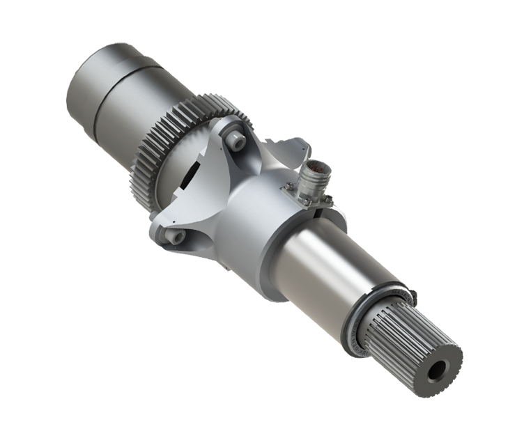
Sensor Housing Assembly – Redundant magnetic field sensor arrays are contained in a housing designed to accurately and repeatably locate and maintain the position of the magnetic field sensors with respect to the transducer shaft. The housing assembly used by the LCAC torque-meter is constructed of hard anodized aluminum. A sleeve composed of electroless nickel plated AISI 1018 steel is placed symmetrically about the magnetic field sensors and acts to shield them from external parasitic magnetic fields, thus increasing the overall signal to noise ratio of the torque-meter system. Each magnetic field sensor array is independently electrically connected for redundancy. The sensor housing assembly is located about the transducer shaft, which again, is the pre-existing engine output shaft. A photo of the installed sensor housing as configured for dynamic testing is shown.
Circuit Design – As in other applications which require accurate measurement of magnetic fields using saturable-core type magnetometers, a dedicated driver and signal conditioning circuit is required. Based on conventional saturable-core magnetometer measurement technology, the circuitry was developed by MagCanica for the polarized band torque-meter system, and customized to accommodate the requirements of the LCAC application. The circuit carries out functions specific to the magnetic field sense elements and their orientation within the sensor housing to accurately determine the amplitude and direction of the torque-induced magnetic field. Additional operations are carried out within the circuitry, including filtering, amplification, and conditioning the output from a voltage format into a 0mA to 20mA current loop format, used as the standard means of transmitting signal information across long transmission lengths (>20m [>65ft]) required for the LCAC craft installation.
Packaging – While other packaging options are available, including integrating the electronics into the sensor housing assembly, the discrete, disconnect-able signal conditioning module used by the LCAC torque-meter constitutes an architecture that provides modularity as well as redundancy, i.e. two channels, through dual electrically independent signal-conditioning circuits that are located within the sealed module. The signal conditioning module (SCM), shown in Figure 5, is relatively small, weighing only 260g [0.57lb]. As described in the Mil-Spec Testing section, prior to entering into service, the module (as well as the torque-meter housing) had to be qualified for a wide range of environmental and electromagnetic interference tests. Therefore, it was designed and manufactured accordingly. The module is certified to operate across the LCAC’s rated temperature range of -35ºC to 121ºC [-30ºF to 250ºF].
MIL-STD-810F Environmental Testing:
As described by specific MIL-STD-810F testing procedures, the polarized band torque-meter was required to pass environmental tests deemed appropriate by the Navy, summarized in Table 2. Because environmental testing represents field life versus real-time operational fidelity, real-time monitoring of the equipment while under test was not required during the environmental MIL-STD tests. Therefore, each environmental test concluded with an operational check of the torque-meter hardware to ensure proper operation.
MIL-STD-461E Electromagnetic Testing:
While most sea-based gas turbines reside in specialized enclosures designed to suppress noise and absorb stray electromagnetic interference, the LCAC prime movers reside in modules integrated into the aluminum superstructure making them more susceptible to external electromagnetic interference. Criteria for electromagnetic interference drew from existing surface ship requirements, specifically the MIL-STD-461E tests specified in Table 3. Each of the electromagnetic testing sequences occurred with the torque-meter powered. Testing mandated real time monitoring of the nominal output to ensure noise and external influences would not interfere with the engine control unit algorithms. An additional operational check was performed following the completion of each test.

Table 2 Summary of MIL-STD-810F Testing

Table 3 Summary of MIL-STD-461E Testing
While stable operation using water-brake dynamometers demonstrated the basic functionality of the polarized band torque-meter system, integration into the craft transmission introduced numerous variables associated with each of the drive-train components requiring the system to be run in a more fully representative configuration. Testing on board the actual craft thus allowed integration of the system with the remainder of the LCAC drive train and the associated control system tuning and development. Some samples of this testing are described below.
Phase I Testing (Data Acquisition):
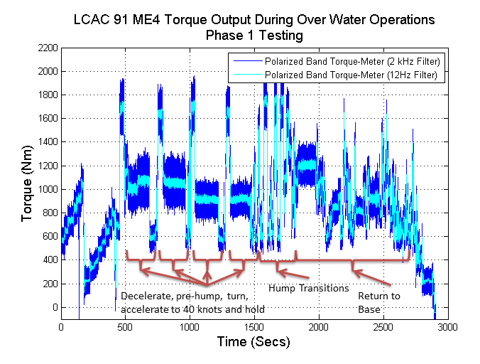
The first phase of boat testing was carried out with the objectives of (i) proving out the functionality of the polarized band torque-meter on board the craft, (ii) collecting data at high sampling rates to look for resonance frequencies or transient torque events with high magnitudes, and (iii) characterizing the drive train dynamic response in order to properly tune the closed-loop-torque-control algorithms to be used for engine power balancing. A conventional strain gauge based torque-meter, installed on customized transmission shafting, and provided a reference value to compare against. Operation at each of the various craft power levels as well as transient response associated with drive train speed changes and propeller pitch changes provided information about the main loads (lift fans and propellers).

Figure 15 Data collected during Phase I boat testing. Data collected shows LCAC acceleration, hump transitions, and return to base

Figure 16 Data collected from torque-meters installed on Main Engines 1 and 3 while power balancing is enabled based on the torque measurement from the polarized band torque-meter
Conclusion
Significant development and application engineering of the magnetoelastic polarized band torque-meter technology has allowed for its successful integration and testing on the LCAC for engine control applications. The current state of the project is that MagCanica successfully qualified the system, and has now delivered nearly the full production quantity required to instrument the US Navy fleet. The system is now being used in closed-loop torque control to optimize the fleet’s power delivery and expand mission profile capability.

